Standing Walls Without Heavy Equipment
Why do we need to stand walls, anyway?
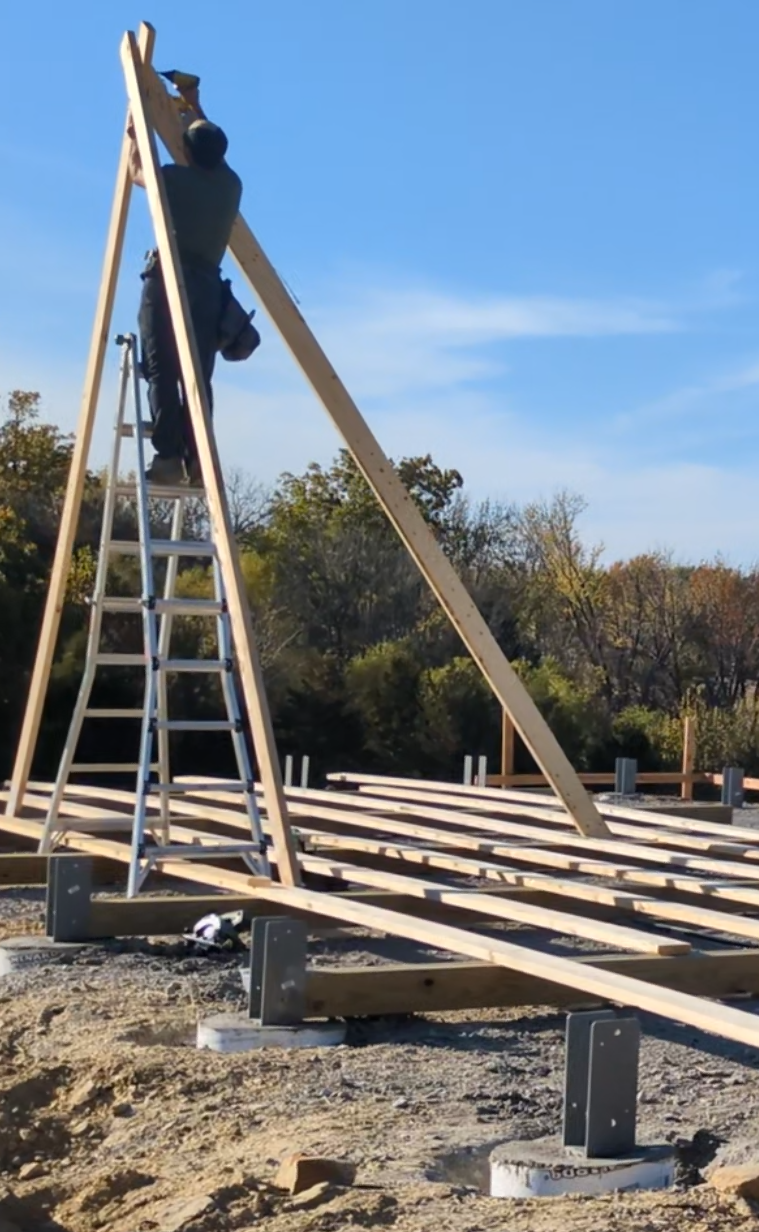
If you’ve ever framed a wall on a ladder or from a lift, you probably wouldn’t be asking this question. The safety, the time spent moving said ladder or lift and swinging a hammer sideways all day - not very pleasant. Why do that if we can frame walls on the ground, nailing from a safe and comfortable position, standing them up in a few hours?
I can even argue it’s an additional reason to pour concrete piers and wet-set column brackets (not the main reason but a reason nonetheless). It can speed up construction and save on labor costs.
No machine, what now?
If you don’t own a crane and don’t want to shell out a couple grand to rent one, you’re not alone. Us humans were building big stuff before we had these machines anyway - they just speed things up.
Google tells me one horsepower is 550 lb ft / s. I take that to mean one horse can pull 550lbs a distance of one foot in one second. I don’t have a horse but I have a winch, so what would it look like if we pulled up this 48 foot long, 16 foot tall post-frame wall with a winch?
The sliding problem
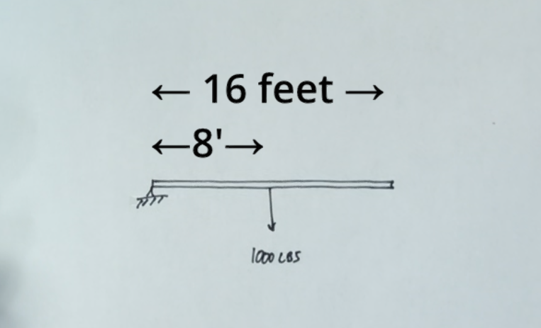
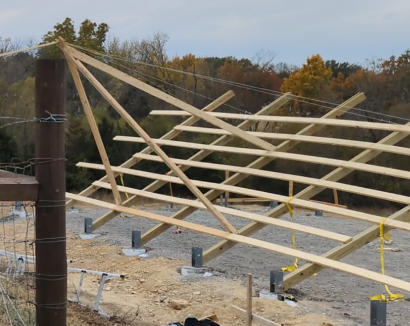
Here’s our wall. We know the shipping weight of the lumber - Let’s keep it simple and say it weighs 1000 lbs.
To move an object you have to apply a force larger than whatever force is holding it in place. In this case, gravity is holding our wall to the ground and giving it weight. If we imagine the wall as a beam, we can put that weight right in the center at 8 feet.
I’ll admit this is quite the simplification. But I think breaking down problems into a simpler form is a great way to think about them.
Here we can see the torque applied from the wall’s weight around our brackets if we tried to lift it from the right side. Torque = force * distance, so the torque of the wall is 8000lbft.
Any effort to stand the wall must overcome that torque (like 500lbs at 16ft).
Because we don’t have a machine, our only option here is to pull the wall up from the left side. This of course assumes we have the room to do that - i.e. 50ft without obstructions on the outside of our building. In this case we have that luxury.
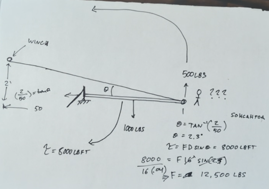
So what if we hook up to a winch mounted on a pickup truck? Let’s say that winch is 50ft away and two feet off the ground.
There’s no way around it, the way things are set up here, that wall is going to slide. So let’s hypothetically bolt our columns into our brackets to keep it from sliding.
When you exert a force on an object (the wall) with a fixed position (the brackets) at an angle (the winch location), the equation for torque becomes T=FDsin(𝜃).
Unfortunately for us, this drammatically increases the force required at the winch to overcome the torque of our wall.
If we hold the wall barely off the ground, the torque created by the winch would be equal to the torque created by the weight of the wall because the wall isn’t moving (this is static equilibrium, for reference later).
That means we can use the torques interchangeably for the sake of finding the minimum force required at the winch to keep the wall off the ground. That is, we can replace the winch torque from the last equation with the wall torque (which we know is 8000lbft), allowing us to solve for the force at the winch.
That’s just too much weight for any winch I’m willing to use.
Disclaimer: I pulled this wall up from the draw-bar hitch of my tractor because that was the most convenient option at the time, so I didn’t actually use a winch at all. But even my tractor doesn’t weigh more than 5000lbs so this setup would easily have the wheels spinning in the dirt.
Back to the drawing board.
There are a lot of different ways to think about a problem like this. Most of them that came to my mind involve some sort of thinking in the realm of engineering statics. Also known as the structural analysis of objects at rest. There are a few statics concepts that can help us get an idea of how much weight we will be dealing with on the line. Our scenario actually looks a lot like the famous hanging sign problem, just turned on its side:
The way I ultimately landed on solving for my brace was with sliding vs tipping.
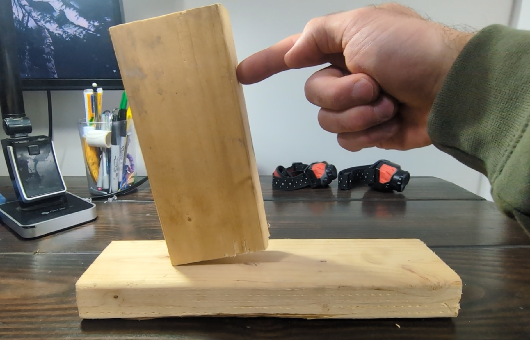
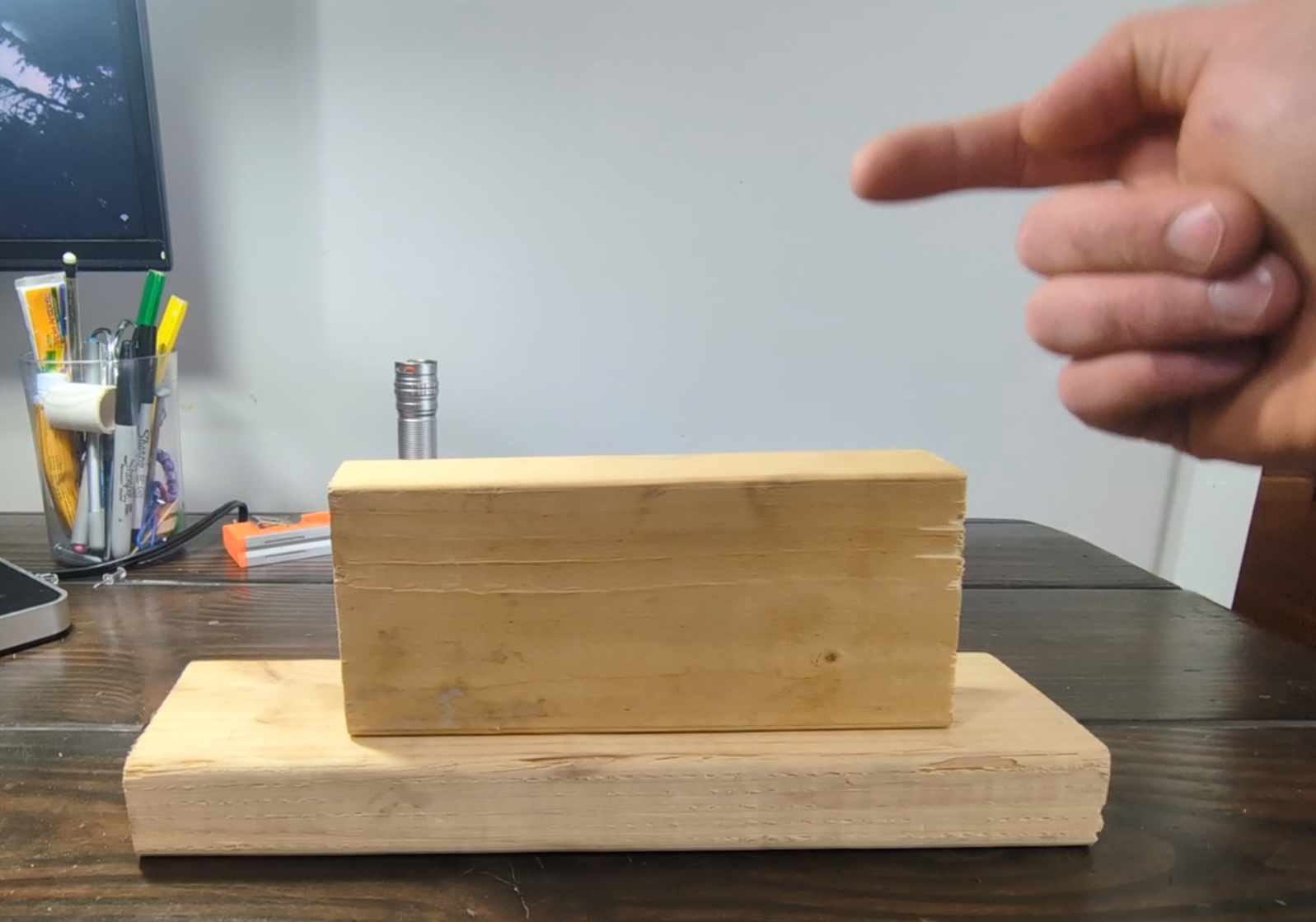
This block will slide if I push on it near the bottom.
But if I increase the height of my finger, I can find a sweet spot where it tips, instead of slides.
Let’s call this height H.
What if the block was on its side?
Height H is well above anywhere we can actually push on the block.
We have to find a way to push the block at height H if we want to get it to tip over.
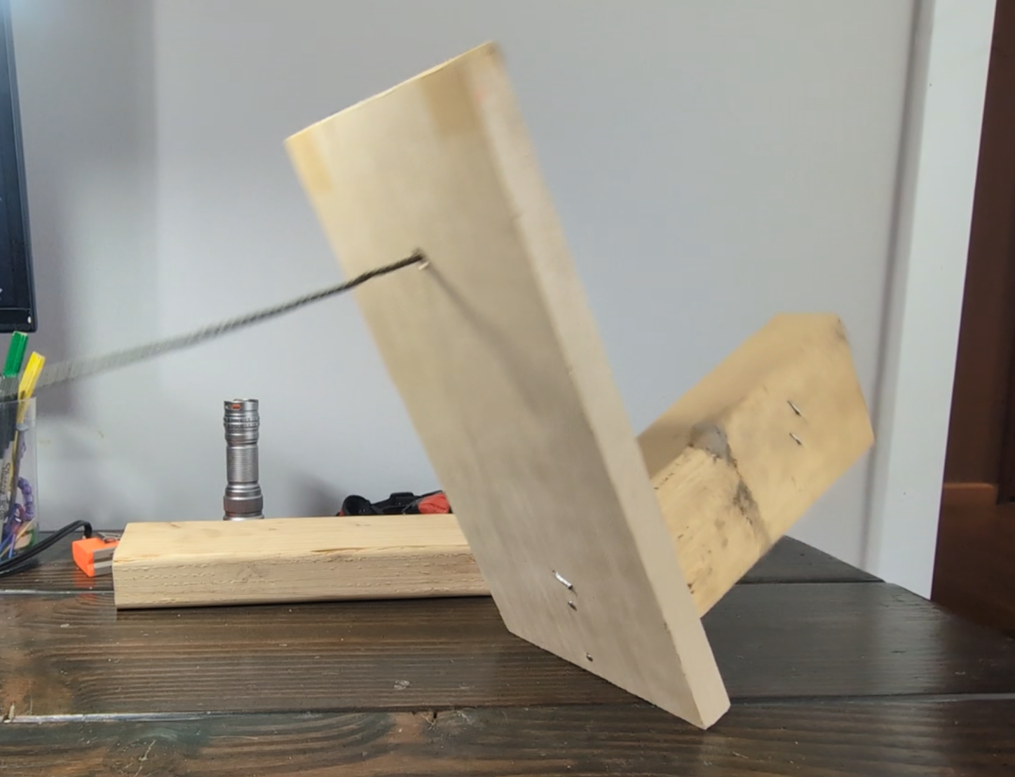
We need to add a lever arm.
This allows us to push on the block at the height required for tipping.
The moment an object tips instead of slides, it is in static equilibrium, as referred to earlier.
When an object is in static equilibrium, all the torques and directional forces appiled to an object cancel out. The thing isn’t moving (or in this case the type of movement is transitioning).
We usually know how to calculate at least some of these forces and torques individually, and we can use that information along with the premise that they are directionally equal, to calculate any missing values i.e. the forces we are solving for. Here’s what that looks like for us:
When the block transitions from sliding to tipping, the directional forces i.e. F(x) are equal and opposite (think the friction on the block and my finger).
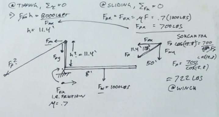
In the case of our wall, we can estimate the friction force based on the weight of the wall and a coefficient of friction (m).
I used 0.7 as the coefficient of friction here, which can be loosely described as steel on steel. Our materials in contact are the treated wood columns and the powder-coated steel brackets. This number is really someting that should be measured, but I kept things simple and made an educated guess. I know it is more slippery than rubber on concrete (m = 1.0), and less slippery than ice on ice (m = 0.1).
We get 700lbs for the x direction of the force applied by the winch at the top of the lever arm. We can substitue that into our equation for torque under the premise that the torque created by the winch is equal to the torque created by the wall, and conclude that our minimum brace height is 11.4ft.
Now we can use SOHCAHTOA to cacluate the hypotenuse force vector using the angle of force (50ft away, 11.4ft high), and known x directional force found in the last step.
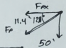
This is the force at the winch, and our calculations give us 722lbs.
Now that’s a number we can work with!
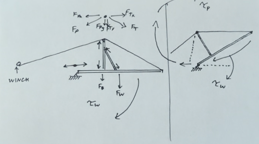
The connection between the lever arm and the brace is pretty weak so I move the brace up on the wall and add a reinforcing member and run cables through the brace on to the top of the wall. This allows us to pull the top of the wall up, while forcing the base of the wall into the brackets.
Moving the brace complicates the math but I can tell you from experience that the force at the winch is pretty close to what we calculated before.
This is all still theoretical at this point, so I’m going to be safe and say we need 1000lbs at the winch and 1000lbs in the cable to lift the wall.
In reality the wall’s weight is distributed along the 48ft of wall so I used rigging cable to hook on to 4 of the 5 columns and ran two straps through the brace to keep the load balanced.
And that’s all there is to it!